Vanderbilt University
Center for Structural Biology
- Introduction and Scope of Manual
- Vanderbilt Crystallography online
- Automated Crystallization PAC-Van
Facility summary for NIH grants
- Bruker Diffraction Laboratory
Access to in-house diffraction
Care and maintenance of dry shippers
INTRODUCTION AND SCOPE OF MANUAL
This manual addresses practical aspects of doing crystallography on the Vanderbilt campus through the crystallography facility which is a part of the Vanderbilt University Center for Structural Biology (CSB).
Subject matter is organized into chapters dealing with specific functions. The facility web pages are in the first chapter of the manual followed by the automated crystallization facility, PAC-Van and the MRB 3/Biological Sciences Building diffraction laboratory, and using the synchrotron beam lines at LS-CAT in the final chapter.
The manual is also meant to assist users in the event of an instrument problem when the facility manager is not available. In all cases, when an issue with the facility is noticed, please report it right away. If you are not sure or not comfortable performing an operation on any system, please leave it for the manager. The manager, Joel Harp, is reachable by cell phone at 615-818-4637 or by email joel.harp@vanderbilt.edu.
Access to Instrumentation
Access to facility instrumentation is available to all researchers on the Vanderbilt campus. For researchers familiar with crystallography, access to instruments is available by contacting the facility manager who will provide the necessary training for operation of the instruments. Costs for using the instruments is assessed based on usage in the previous year and is a flat fee varying by usage tier. The crystallography users faculty committee meets quarterly to discuss, among many other issues, the costs for each usage tier.
For researchers unfamiliar with crystallographic techniques, access to equipment and expertise is available through the Center for Structural Biology Outreach program. Contact may be made either directly with CSB faculty or staff or through the on-line form at http://structbio.vanderbilt.edu/access.php. To find the form from the facility home page, click on "How to Access the Facility" and then on the link for the "Outreach form." Following the initial contact, a project may be initiated with the intention of either establishing a collaboration with current crystallographers or beginning a project requiring training of a new user in the crystallography facility. New users will then be required to attend training based on this manual and individual instruction and check-out on the instruments. See the appropriate chapters for additional information on using diffraction instrumentation or crystallization robotics.
VANDERBILT CRYSTALLOGRAPHY ONLINE
A web interface for the facility may be found within the pages of the Vanderbilt University Center for Structural Biology by directing a browser to http://structbio.vanderbilt.edu/xtal/. An effort has been made to standardize the appearance and functionality of web pages throughout the CSB. The header for the web page is kept the same through nearly all CSB pages and contains navigation shortcuts that can be accessed by mouse clicks within defined regions of the image as shown in the following figure.
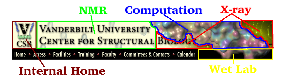
Navigation through the crystallography facility web pages is simplified using the navigation side bar that presents the main subject headings from the crystallography home page. Navigating to any one of these major subject pages will open appropriate sub-headings on the navigation side bar. Again, the header and footer provide shortcuts to areas within the CSB and to the VU home page.
The home page for the Crystallography Facility has a color coded key to rapidly determine the status of equipment in the facility. The names of the pieces of instrumentation are listed across the bottom of the page in either red, green, or salmon. Green indicates that the instrument or robot is functional and available for use. Red means that the instrument or robot is not available for use and salmon indicates an advisory for use of that piece of equipment. Clicking on the name will bring up a window specifying status.
COMPUTATION
All software necessary for every stage of a structure determination project is available through the Center for Structural Biology, CSB. Vanderbilt is a member of the SBGRID consortium. Software is maintained by sbgrid and accessible from any CSB computer with a CSB unix account. Information about the software maintained by sbgrid is available on the website http://sbgrid.org.
Requesting a unix account
New users should immediately obtain an CSB computer account. Follow these steps to obtain a CSB unix account:
- Point your web browser at the secure site https://structbio.vanderbilt.edu/useradd
- Login: sbrequest
- Password: welcomevsb
- Fill out the online form completely. You must specify an email address that you use frequently (preferably a Vanderbilt address) so that CSB mail will get forwarded to you.
- A system administrator will activate your account within 2 business days. You will receive an email confirming your new account along with instructions for obtaining additional information about the account.
- While you wait for your user account to be activated, please browse the computational resources available on the CSB website http://structbio.vanderbilt.edu/comp
- If you do not receive confirmation within 2 business days, email admin@structbio.vanderbilt.edu.
Questions? Request Tracker
The Request Tracker, https://structbio.vanderbilt.edu/rt/, is an online resource for handling questions, issues, and requests involving anything computational. To have a question answered or a request dealt with, log in the Request Tracker using a VUnet ID and password. At the top of the page is a drop down menu for the appropriate "queue" to be used.
The "support" queue is used for any questions, issues, or requests involving general computation. The "xtal" queue is used for questions, issues, or requests specific to crystallography at Vanderbilt. Submitting a ticket in a queue will launch a request that is automatically acknowledged and then answered by CSB system administrators or by the crystallography facility manager.
There is a "CSB Outreach" page that is occasionally, mistakenly, used to submit questions or requests. The outreach page is specifically for laboratories outside of the CSB to engage with CSB scientists for possible structural studies.
HKL2000
HKL2000 is available but only runs on certain CSB computers. HKL2000 requires a license for each computer running the software. The crystallography facility maintains a license file, cr_info, for all Vanderbilt computers running HKL2000 as well as maintaining site files for all detectors that may be used for data collection at various beam lines around the country.
To set up for processing with HKL2000, set links to the license file and the data base of site files using the following unix commands
ln -s /sb/apps/HKL2k/cr_info ~/cr_info
ln -s /sb/apps/HKL2k/hklint ~/hklint
It sometimes happens that hkl2000 will launch but the listing of detectors is empty even after issuing the setup commands. This can occur if the user has a previous hklint directory in the home directory. To correct this, issue the following unix commands.
rm -rf ~/hklint
ln -s /sb/apps/HKL2k/hklint ~/hklint
Several computers are available for running HKL2000 including kraken, x8r, and x8l as well as other machines associated with specific laboratories. To use HKL2000 remotely on the computers issue the following unix command for kraken, for instance, to launch the program within one's unix account. The program can then be launched using the command "hkl2000."
ssh -CY username@kraken
For issues with HKL2000, contact Joel Harp (joel.harp@vanderbilt.edu).
AUTOMATED CRYSTALLIZATION PAC-VAN
The Protein Automated Crystallization facility at Vanderbilt, PAC-Van, provides training and access to robotics to make crystallization experiments easy and effective. The robots in the PAC-Van facility are available to all researchers at Vanderbilt University. Robot provide the most effective means to screen a large number of conditions, particularly in the early stages of a structure project and easily lower the "activation energy" for any structure project project by making screening simple, reproducible, and fast. The Mosquito nanoliter drop setter robot precisely dispenses volumes in the 200 nanoliter range making it possible to screen 96 conditions with as little as 20 mls of purified protein. For a concentration of 10 mg/ml, that would mean setting up a 96 condition screen with only 0.2 mg of protein.
The RockImager robot is valuable for rapid evaluation of crystallization results and for maintenance of data on crystallization experiments. Images and data are available for any experiment using a web browser. The ability to examine images collected over the time course of the experiment is especially useful. The software allows for the scoring of experiments and queries of the crystallization data accumulated for a structure project.
Access to PAC-Van
The robotics in PAC-Van are available to all researchers at Vanderbilt after on-site training with the facility manager, Joel Harp (joel.harp@vanderbilt.edu). The first training session is typically scheduled for a Friday afternoon. Operation of the robots and set up of user accounts are covered in the first session. The first session does not typically involve the actual setting up of a crystallization experiment. Once the preliminary session is complete and all materials are ready for use, a second session will be scheduled for the purpose of setting up real experiments with the facility manager on hand to offer direction and answer questions.
The PAC-Van facility is located in the Iverson laboratory and may be locked during off-hours. If access is needed during off-hours, a key to the door may be obtained from Room 476 Robinson Research Building.
Users of the facility should also be good citizens and remove expired plates from the RockImager as soon as they become expired. The software automatically reminds users of the presence of expired plates by email. Expired plates occasionally occupy a majority of the storage in the imager so it is important to keep up with this duty. Any plates left expired for more than a month may be removed and discarded without notice.
Robots
Xantus LCP Robot
The Xantus automated liquid handling platform (Zinsser) is a modular robotic pipetting platform designed for preparation of lipidic cubic phase (LCP) crystallization trials for high-throughput membrane protein structure determination.
- Deck footprint (SBS-based) is compatible with standard hardware used in protein crystallization (96-well 2 mL deep-well bocks, 96-well micro-titer plates) eliminating the need for expensive, custom hardware.
- Flexible deck layout accommodates experimental customization.
- 8 probes with independent liquid detection controlled by an integrated pump system capable of dispensing 1 nL to 2 mL sample volumes.
- Freedom of movement of the probe arm in 3 dimensions (x, y, and z).
- Efficient setup time: 7-9 min per 96-well plate
- Minimal sample consumption: 5-10 µL of protein sample per 96-well plate
- Initial screening and condition optimization are performed using a single program method.
- User-friendly, GUI-based software controls all the robotics, which allows for safe and reproducible experimental conditions.
Mosquito Robot
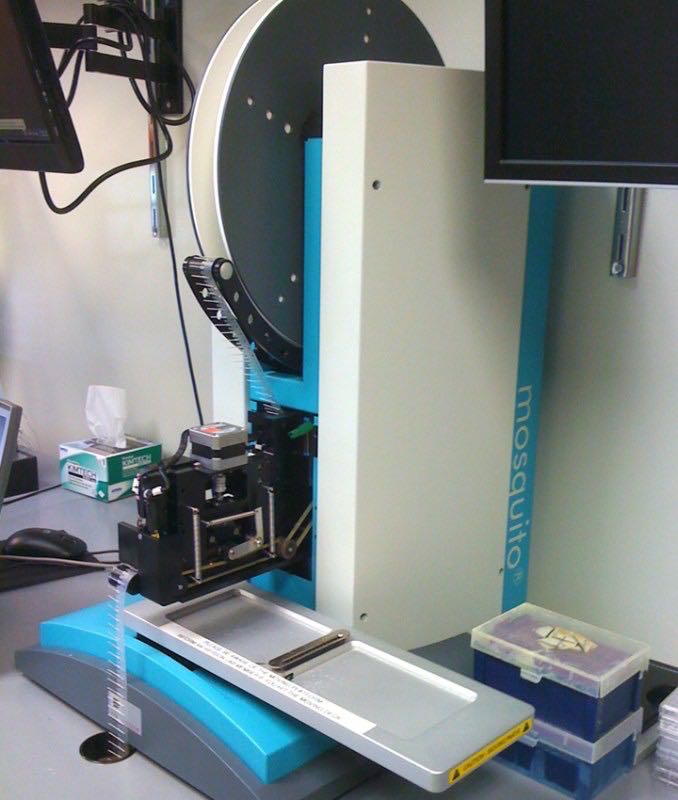
Crystallization trial experiments can be performed quickly and efficiently in 96 well plates, using the Mosquito, a nanoliter dispensing high-throughput robot.
- Uses disposable tips on a reel to dispense the sample from an 8-slot strip and a 96-well tray to a single drop in a sitting or hanging drop setup.
- Offers the ability to use a small amount of protein/DNA in high-throughput broad crystallization screening with no cross-contamination.
- Ratio of sample: solution, drop size, and number of samples per tray can be altered for each screen.
- Efficient setup time: 2 min per 96-well plate
- Minimal sample consumption: 10-50 µL of protein sample per 96-well plate
Videos: Overview and How The Mosquito Works.
Rock Imager
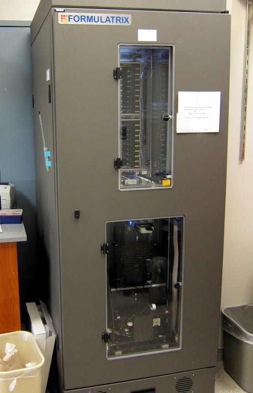
This is a robust, easy-to-use, automated imaging system for protein crystallization.
- Incubates and captures superior quality images of up to 1000 micro-titer plates on a user-defined schedule.
- Supports 500 LCP plates in addition to the above mentioned 1000 micro-titer plates.
- Collected images can be viewed remotely from any computer with a web browser.
- UV imaging uses the fluorescence of tryptophan under ultraviolet light to help determine if a particular crystal is protein, and aids in finding hidden crystals not visible with bright-field imaging.
Crystallization plates
A wide array of commercially available screens are typically used to begin a structure determination project. These screens are expensive and purchase of a 10 ml format screen for a limited number of projects can be wasteful. Pre-prepared trays containing commercial screens are available in the PAC-Van facility to be used in individual 96 well format crystallization trays. This precludes the need to purchase expensive screens in order to perform just a few screening experiments.
When setting up an experiment using these plates, select the appropriate screen from the "Screen" menu in RockMaker and drop-and-drag onto the experiment plate canvas. Right clicking on the tab on the upper left corner of the canvas will provide access to layers. Make sure that only the correct screen is on the canvas.
This also allows specification of the second drop by selecting Protein Layer 1, copy and paste back onto the canvas and rename as Protein Layer 2. The names of the layers can be modified to suit the experiment. Similarly, if you are only using one drop, delete the second protein layer to save imager time. Just check to see that the correct drop position is indicated on the layer menu.
Important Caution The sealing film on the completed crystallization plate must be carefully trimmed to prevent snagging on the transfer arm in the imager.
Screens
The screens currently available in PAC-Van are:
Hampton HT
Hampton Index
Hampton PEG/Ion
Wizard I/II
Emerald Cryo HT
JCSG+
JCSG Core Suite 1
JCSG Core Suite 2
JCSG Core Suite 3
JCSG Core Suite 4
All screens are in MRC2 plates sealed with Molecular Dimension SureSeal films. The cost per plate is currently $30.27.
Referencing PAC-Van
When publishing research that has involved the use of the PAC-Van facility, please include an acknowledgement similar to the fallowing: A portion of the experiments described here used the Vanderbilt robotic crystallization facility which was supported by NIH grant S10 RR026915.
Facility summary for NIH grantes
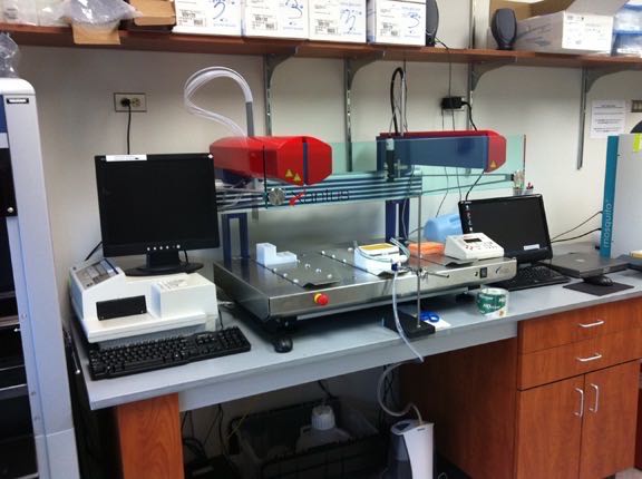
High-throughput crystallization robotics
The Vanderbilt Center for Structural Biology includes a high-throughput crystallization facility with four integrated components: 1) a Hamilton StarLet liquid handler; 2) a Mosquito nano-liter drop setter; 3) a Xantus Cubic Lipid handling robot; and 4) a Formulatrix RockImager imager with UV fluorescence detector. These robots are located on the 4th floor of the Robinson Research Building in a 400 ft2 temperature-controlled room, currently maintained at 20°C. Bar-coding coordinates the information transfer between robotic instruments, which can be operated remotely through the network. The automated crystallization facility has improved the efficiency of making crystallization screens, increased the speed of initial crystallization trials, decreased the amount of sample need for crystallization, decreased the amount of time required to analyze the crystals, and decreased the rate of false positives. Training on the instruments maintained within the robotic facility is available through individual consultations.
BRUKER DIFFRACTION LABORATORY
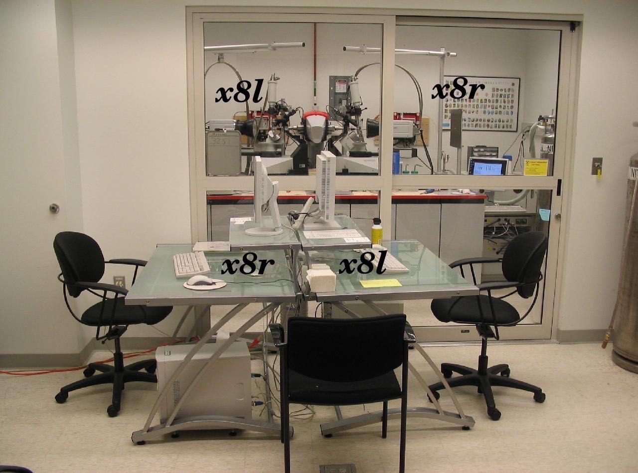
On entering room 5263, the X-ray system is housed in the bay to the left. The bay to the right is a crystal growth and handling room. The computers in the open area are control stations for the two detectors, x8r and x8l. Notice in figure below that each of the computers is associated with the detector on the opposite side of the bay. The name x8r refers to the X8Proteum goniometer and detector instrument on the right side of the bay looking in. The other unit, x8l, is the X8Proteum on the left side of the bay looking in. The x8l system is currently offline.
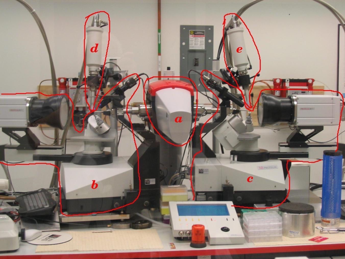
Instrumentation in the Bruker diffraction laboratory consists of the following:
- Generator tower
- X8l
- X8r
- Cryostat head for x8l
- Cryostat head for x8r
Access to in-house diffraction
Access to in-house diffraction is available to all Vanderbilt researchers after first completing on-site training with the facility manager. To arrange training, email Joel Harp joel.harp@vanderbilt.edu.
Following completion of site-specific training, new users will request a user account for the facility either directly from the facility manager or through the online account request form ( http://structbio.vanderbilt.edu/xtal/sched/registration_form.php ). To find the form from the facility home page, click on "Instrument Scheduling", then on "Request Instrument Time". Under the instructions at the top of the instrument time request form, click on the link for "online registration form." Fill out the boxes and click on the submit button. An email will be generated automatically and sent to the facility manager for action. The manager will then enter the data into the facility database and respond with an email welcoming the new user and instructing the new user to subscribe to the xray mailing list.
Online Scheduling
Requests for instrument time may be made by registered users through the on-line request form. The home page for the facility, http://structbio.vanderbilt.edu/xtal, provides links to access the request form, the request queue, the instrument schedule calendars, and pages for current instrument status.
When requesting instrument time, first check the instrument calendar to determine dates of availability.
Safety Features
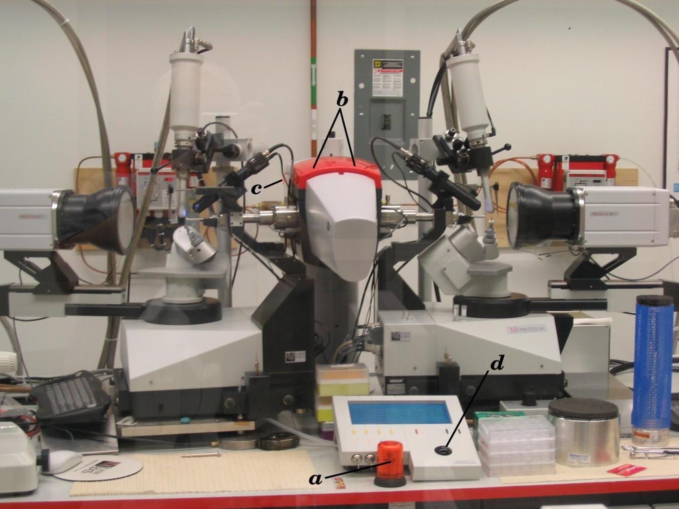
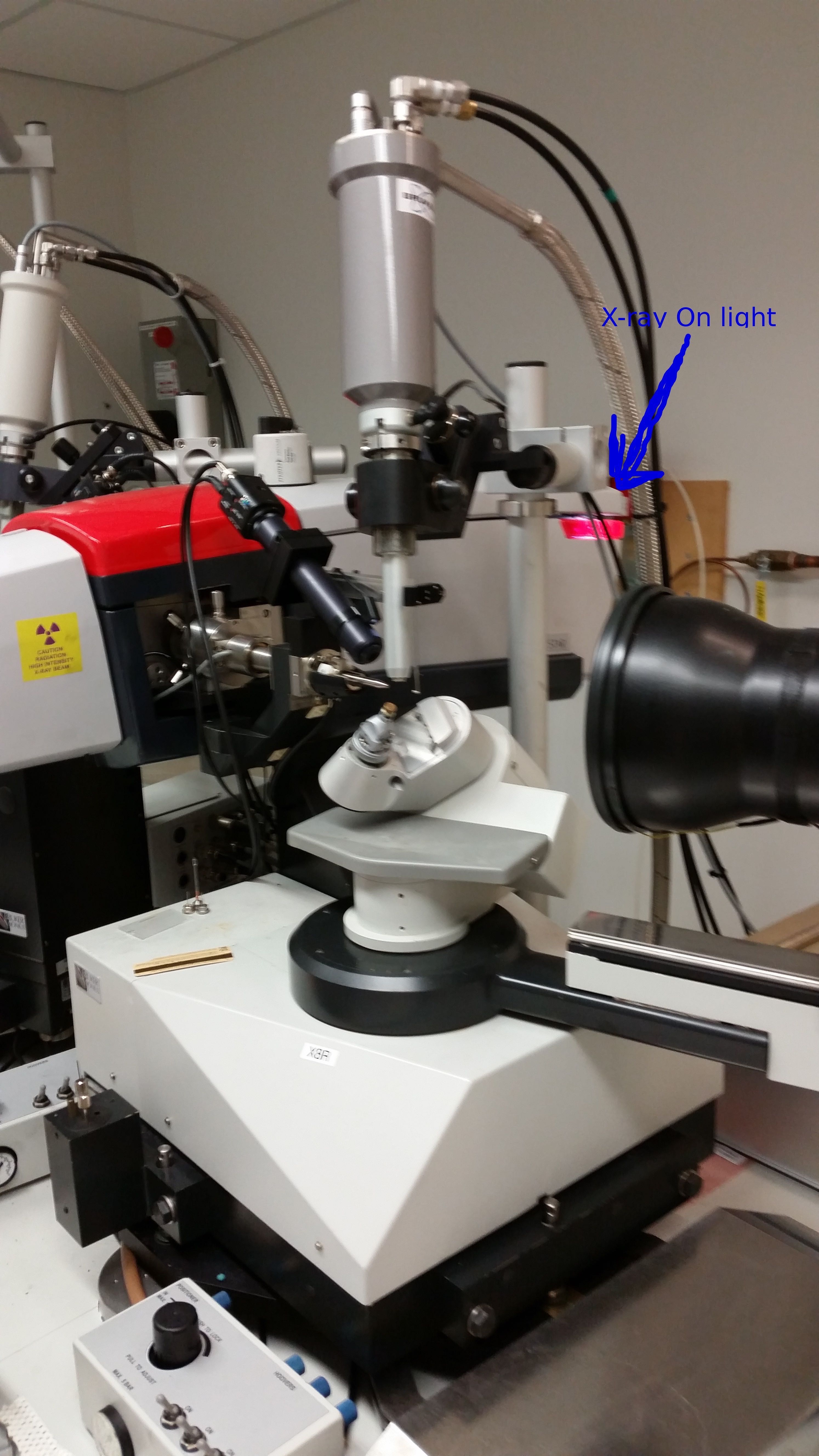
Location of indicator lights: a) Safety by-pass on/off lamp b)Shutter open light c) X-rays On light.
Safety features include indicator lights to indicate X-rays on and shutter open conditions. One issue is that the shutter open lights on top of the tower may not be sufficiently apparent. The red cowl at the top of the tower has LEDs inside that illuminate when the primary shutter is open. Even when this lamp is illuminated, X-rays may or may not be emitted depending on the status of the timing shutter located at the end of the X-ray optics. This shutter is indicated by a single small LED. The safety by-pass indicator will flash when the safety switch on the enclosure door is in the "by-pass" position. If the switch is in the "off" position, a magnetic reed switch will detect if the doors are open or closed and prevent the shutter from opening with the door open.
Measurement of radiation field at full power with both shutters open have indicated that exposure at 30 cm from the location of the crystal at a right angle to the direct beam is in the 1 mRem per hour range. Therefore, badges are not needed or provided. Even so, please exercise due caution whenever working in the X-ray diffraction laboratory.
BIS:Bruker Instrument Service
The Bruker program, BIS, which stands for "Bruker Instrument Service," is the server application that actually runs the X8. When the Proteum2 gui connects to the server, it is connecting to the BIS application and the status of the connection can be seen by lights on the BIS gui. It may be necessary to stop and exit from BIS prior to rebooting the server computer. This is sometimes necessary is there has been a collision detected or a missing beamstop.
To stop BIS, first click on the "Stop BIS" button at the bottom of the gui. Then click on "EXIT". Watch for the X8 to go through a ``parking''routine prior to shutdown of BIS. A clean shutdown is much more desirable but, occasionally, it may be necessary to kill the BIS application when the X8 will not go through the park routine. This will mean a longer restart but should not cause a serious problem.
Restart BIS by double clicking on the BIS icon on the desktop. The first window to open will be the Kappa control gui. The Kappa Control application is a front-end to BIS that will initialize the kappa goniometer by first finding the zero position of all four circles and the detector distance. This can be seen on the gui as "GONZERO". Once the X8 is initialized, the BIS gui will pop up. This may take some time so be patient. BIS is now started and ready to accept connections from PROTEUM.
Accessing data remotely
Diffraction images are written to a data disk on the client computers, x8r and x8l, using samba and go into the /smb/x8r/frames directory. Each user has a data directory to store images and processing files. The frames directory is NFS mounted to be accessible as a read-only file from any CSB computer at /sb/x8r/ or /sb/x8l/.
Some notes on angles
The kappa-axis goniometer allows for more efficient data collection than a single phi axis. Four separate angles are available (see figure below) to position both the crystal and detector for the most efficient sampling of reciprocal space or for positioning reciprocal space axes for oriented diffraction views. The kappa-axis goniometer also allows for easy alignment of an indexed crystal for oriented scans. The 2-theta arm allows for movement of the detector to high angles to collect data to resolutions of greater than 1 Å.
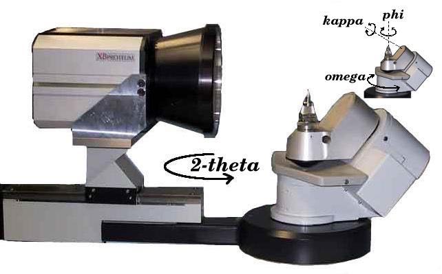
One issue that may cause confusion is the use of the chi angle on the Proteum2 gui when setting up a data collection scan. The kappa-axis goniometer is a variation of the traditional euler cradle with a full chi circle. The kappa block is mounted at a chi angle of 50 degrees. By various combinations of kappa and omega angles, the kappa goniometer can produce chi-like orientations and allow for mounting of the cold stream for cryogenic data collection. On the Proteum2 Experiment spread sheet, the chi angle column allows the user to specify the chi-like orientation without having to do the complex calculations needed for the appropriate kappa and omega angles.
Troubleshooting
This section will provide guidance to deal with simple issues that may be encountered when using the Bruker system. In general, the best course of action is to call the manager, Joel Harp, at 615-818-4637.
Please note the red PANIC button at the front of the Bruker under the control panel. If there is a serious issue such as smoke or water pouring forth from anywhere, hit the button and exit the X-ray bay to call the manager.
- Diffraction image is blank: Check that the X-rays are on and at full power. See "Restarting X-rays"
- In, Proteum at the instrument console, no buttons appear to have any effect: Minimize the video gui to see if there is a dialog box waiting for a response. The video gui is set to always be the top window and may be hiding the dialog box. Nothing will happen until the dialog box is closed.
-
Restarting X-rays
Before mounting a crystal, check that the X-rays are on. If X-rays are on, the light at the back of the tower will be lit, as below.
We have started having intermittent and unpredictable issues with power fluctuations at night. This is an issue with the X-rays off due to 3-phase mains fluctuations overnight and will cause an error message on the screen of the control panel about either 3-phase mains or a UDC issue. To restart refer to the figures and follow this procedure:
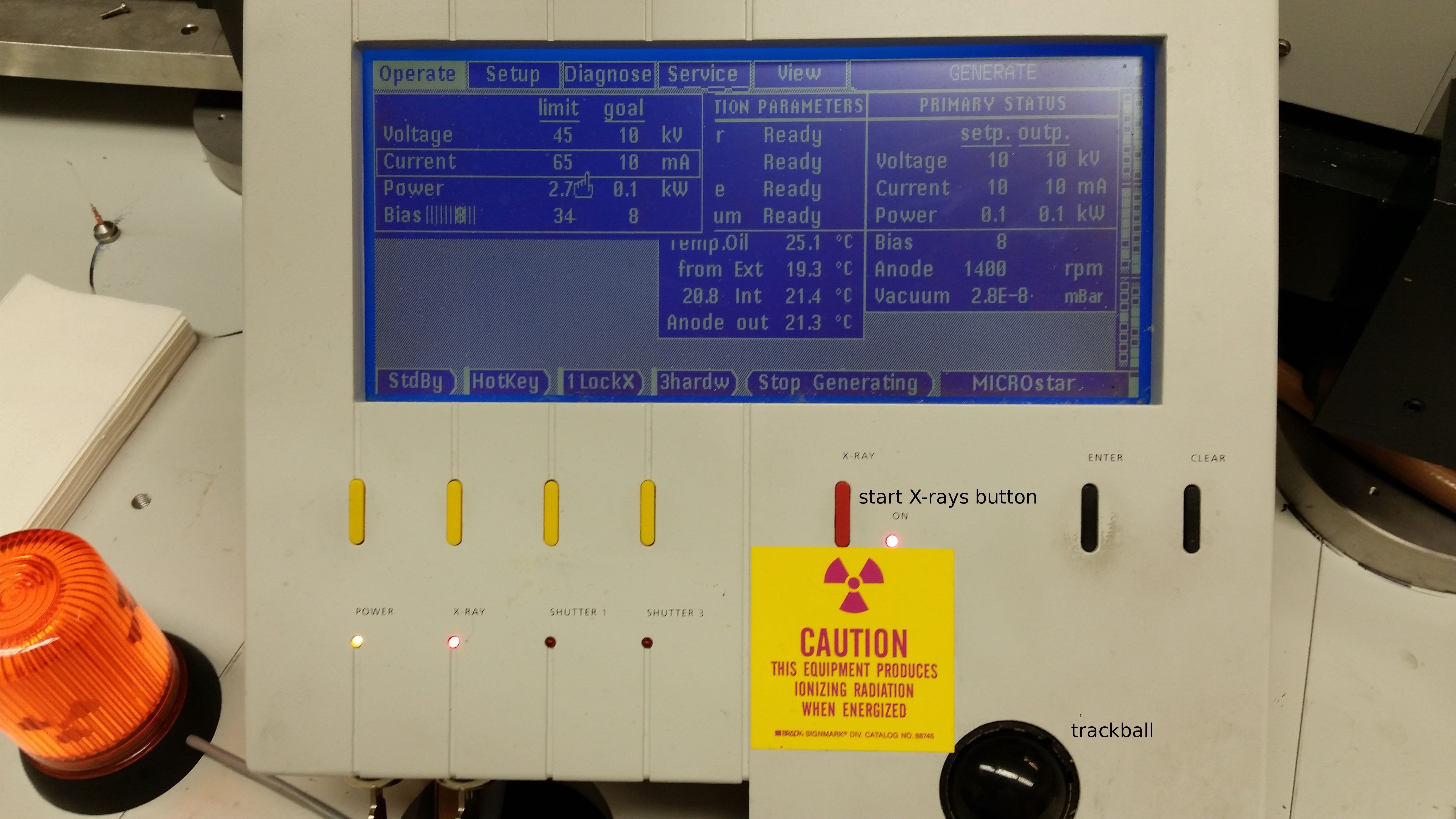
Press "clear" to acknowledge the message.
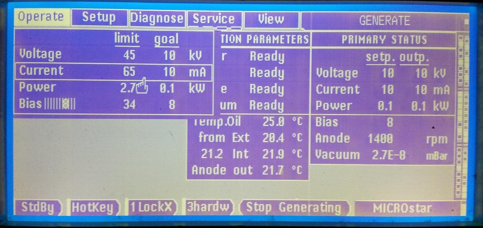
Use the trackball to highlight the "Voltage" line and then use the trackball to set it to 10 kV. Press "Enter
Use the trackball to highlight the "Current" line and then use the trackball to set it to 10 mA. Press "Enter"
Press the start X-rays button and watch for the X-ray ON light at back of tower.
Wait 3 minutes
Power up kV in 10kV increments waiting 1 minute between steps using the trackball to highlight the "Voltage" line and to set the kV. To increment, press the Enter button. Increase voltage to 45 kV
Then use the trackball to highlight the "Current" line and increase current in 10 mA steps in the same manner. Wait 2 minutes between steps. Increase current to 50 mA.
"Anode" should read 6200 rpm and "Vacuum" should be 1-2E-8 mBar
The X-rays are then ready and the panel should look like this: 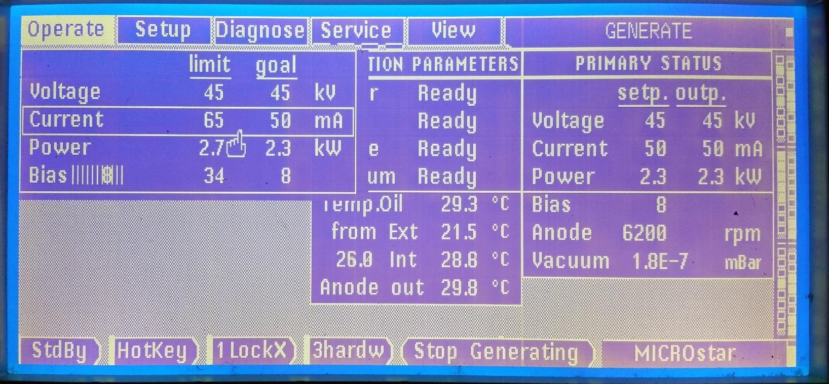
SYNCHROTRON
Available beam lines
Vanderbilt researchers currently have access to three beam lines through membership in the Life Sciences Collaborative Access Team, LS-CAT, in the Advanced Photon Source, APS, at Argonne National Laboratory near Chicago, Illinois. The LS-CAT beam lines are all ID or insertion device beam lines, not bending magnets. Beam line ID-D is fully tunable and is generally reserved for experiments involving SAD data collection. Beam line ID-F is fixed at a wavelength of 0.97872 Å and is suitable for selenium SAD and native data collection. Beam line ID-G is fixed at a wavelength of 0.97857 Å and is suitable for native data collection.
Scheduling for beam time
The beam time for Vanderbilt is arranged during each of three runs over the course of the year. The current schedule can be viewed on the CSB crystallography website under the "Synchrotron Access" tab. Arranging for beam time is done by contacting Joel Harp (joel.harp@vanderbilt.edu) who is currently in charge of maintaining the schedule for Vanderbilt.
Each 12-hr remote shift on ID-F and ID-G will be divided into an 8-hr shift and a 4-hr shift. Once the time is assigned and we know how much time is available on each run, the 8-hr shifts will be divided equitably amongst PIs. The 4-hr shifts and any 'extra' 12-hr shifts on ID-F or ID-G will be 'rapid access time' that can only be requested <2 weeks in advance. This time will NOT (necessarily) be distributed first-come first-served, but priority will instead be weighted based upon equitable distribution of time between the groups and other factors (grant deadlines, etc.).
Students and postdocs will justify the rapid access request with a very short paragraph plus information such as space group, resolution limit, number of samples, wavelengths, etc., that would assist in identifying how much time is required and whether a project should have priority on ID-D. This write up should also include all details that are necessary for submitting the ESAF, preferably in tabular form (we are still requested to submit a single ESAF, and presumably another group will be doing this for the short notice folk). ID-D time will all be 'special request' (not necessarily rapid access) with priority for those that justify the need for multiple wavelengths.
Preparing for beam time
A link to the LS-CAT website is available on that page and users who have arranged for beam time should check the online schedule to determine who is the LS-CAT scientist supporting that beam time and contact the support person ahead of the scheduled time to inform them of any requirements. This is especially useful for ID-D to establish needs for SAD data collection.
Typically, all synchrotron beam time slots are for remote access data collection which means that data collection ends at 10:00 pm Chicago time. On site data collection is easily available and welcomed but will require additional considerations such as additional training at the beam line and housing at the Argonne Guest House.
At least 7 days prior to scheduled beam time, users should file an Experimental Safety Assessment Form, ESAF. This form must be approved before the data collection can begin. The form is filled out online. A link to the form is also available on the crystallography web page or can be accessed at https://beam.aps.anl.gov/pls/apsweb/esaf0001.start_page. Only one ESAF is to be filed from Vanderbilt for each beam time slot. Thus, when multiple groups are using the same slot, one person should coordinate with all other scheduled users and obtain the necessary information to complete the form for all projects involved. This will necessitate each group providing data to the person completing the form. The needed information includes user names, badge numbers, number and kinds of crystals and important method details in the case of SAD data collection.
The ESAF will also list all certifications needed and indicate whether users are in compliance or will need to complete online course certifications prior to using the beam line. Each person scheduled for beam time should verify compliance.
New users should be aware that a badge number and password is required. Registration to become a user of the beam line can be done through the user registration page at https://beam.aps.anl.gov/pls/apsweb/ufr_main_pkg.usr_start_page.
For beam times that are to be shared between groups, be sure to communicate with the other scheduled users to coordinate times within the beam time slot (i.e. who goes first). This detail often contributes to friction between groups and should be worked out well in advance of the scheduled time to keep data collections orderly and efficient.
Once beam time is scheduled, users should consider the shipping date for transferring mounted crystals to the beam line for remote access. FedEx deliveries do not occur on weekends or holidays. Thus, if beam time is on a Sunday, the last opportunity for shipping is an overnight delivery with FedEx pickup scheduled for the previous Thursday. If beam time occurs near a holiday, check with the beam line scientists to determine when to ship. Shipping a day or two ahead of time is not a problem since the beam line personnel reliably maintain liquid nitrogen levels of all dewars present.
Eiger detector
The Eiger detector was installed on ID-D during Run 3 of 2016. Unlike the CCD detectors of ID-F and ID-G the Eiger is a hybrid photon counting detector . Because it is a photon counter, the Eiger produces no readout noise or dark current for an improved signal-to-noise ratio. The detector makes "shutterless" data collection possible.
There are a number of important differences for dealing with the new detector.
- Very Important: To prevent overwriting frames, always give each data set a new directory and name.
- Keep detailed records of data collection parameters for each data set collected. This should include spindle rate, frame rate, distance, and start angle and range. Not all parameters are written into the master file by the detector.
- If you are processing Eiger data using HKL2000, a dialog window will come up asking for the Frame Width and 2Theta. If, for instance, the frame rate is 2 frames/degree then the Frame Width will be 0.5. 2Theta is 0.
- If visualization of real data frames is desired to be displayed on the interface screen, do not collect at speeds greater than 10 Hz (spindle rate * frame rate). At speeds greater than 10 Hz, only every fourth frame will be displayed.
For each data set collected, only two files are written by the detector. One file is the master file that will be named with the data set name followed by ".001_master.h5." The second file will contain the image data with the data set name followed by "_data_000001.h5." HKL2000 will require that the image data be written into individual dbf image files. This is done using the command "eiger2cbf-linux." Issuing the command without arguments will provide instructions in how to convert to cbf. Once the cbf files are written, processing can be done in the usual manner.
Globus GridFTP
The Eiger detector generates an enormous amount of image data. Use of rsync or ftp for transferring data is not recommended. LS-CAT has set up a Globus gridFTP endpoint to allow transfers.
To set up an account with Globus, go to https://www.globus.org. It will be necessary to also install the "Globus Connect Personal" app to set up your computer as an endpoint for file transfers.
By default, the Globus interface will only see a home directory. To use an external drive, it will be necessary to provide the path to the drive in a configuration file. The file will be in your home directory as ~/.globusonline/lta/config-paths. Edit the config-paths file to look something like the following:
~/,0,1
/media/backup/,0,1
This configuration will add the /media/backup drive to the Globus endpoint.
Shipping
Shipping of crystals is done exclusively with cryogenic dry shippers. These steel dewars have an absorbent material that takes up LN2 so that no free liquid is present in the shipper and the shipper can then be classified as "non-hazardous." The typical model is the Taylor-Wharton CX-100 with a hard shell shipping case. The shipping case should be prepared with labels stating "Dry Shipper Non-hazardous."
To prepare the shipper for use, pour liquid nitrogen, LN2, from a 4L transfer dewar just up to the neck of the shipper. Do not overfill the dewar. Close the top with the stopper and wait about 15-20 minutes and fill again. The absorbent material will continue to take up the LN2 until fully charged at which time the shipper core will remain full and be ready to receive pucks containing prepared crystals.
LS-CAT robots accept SPINE baskets. The baskets (often referred to as "pucks") may be obtained from Molecular Dimensions as the EMBL/ESRF sample changer kits (http://www.moleculardimensions.com/shopdisplayproducts.asp?id=288). It is very important to use the correct vials and pins to mount crystals for LS-CAT since the wrong choice can result in the robotic sample changer being unable to mount your crystal on the goniometer. Specifications can be found on the LS-CAT website (http://www.ls-cat.org/pinsCapsVials.html).
Once the samples are packed and ready to ship, either contact FedEx for pickup or deposit the shipper at a FedEx pickup point on campus. Address the FedEx shipping label as follows:
Name of LS-CAT Staff Contact
LS-CAT, Building 436A
9700 South Cass Avenue
Argonne, IL 60439
The staff contact can be found by checking the beam time on the LS-CAT schedule. The initials of the contact are on the calendar and the name can be found on the contact page (http://www.ls-cat.org/contacts.html).
Care and maintenance of dry shippers
In order to extend the life of a dry shipper, the shipper should be dried completely between trips. Place the shipper upside down to allow the cold air to drain and leave it until the entire shipper is warmed to room temperature and thoroughly dried. Leaving moisture in the shipper can cause ice to form when LN2 is next added. The ice formation will damage the absorbent material and reduce the performance and lifetime of the shipper.
Most cases of failure of dry shippers appear to be due to overfilling with LN2 which causes the seal at the neck of the shipper to fail. Failure of the shipper will usually be evident from condensation on the outside of the shipper when charged. This indicates that the vacuum in the dewar is no longer adequate for insulation. A functional dry shipper should maintain cryogenic condition for many days as long as it is kept right side up. A shipper laying on its side will lose cryogen quickly.
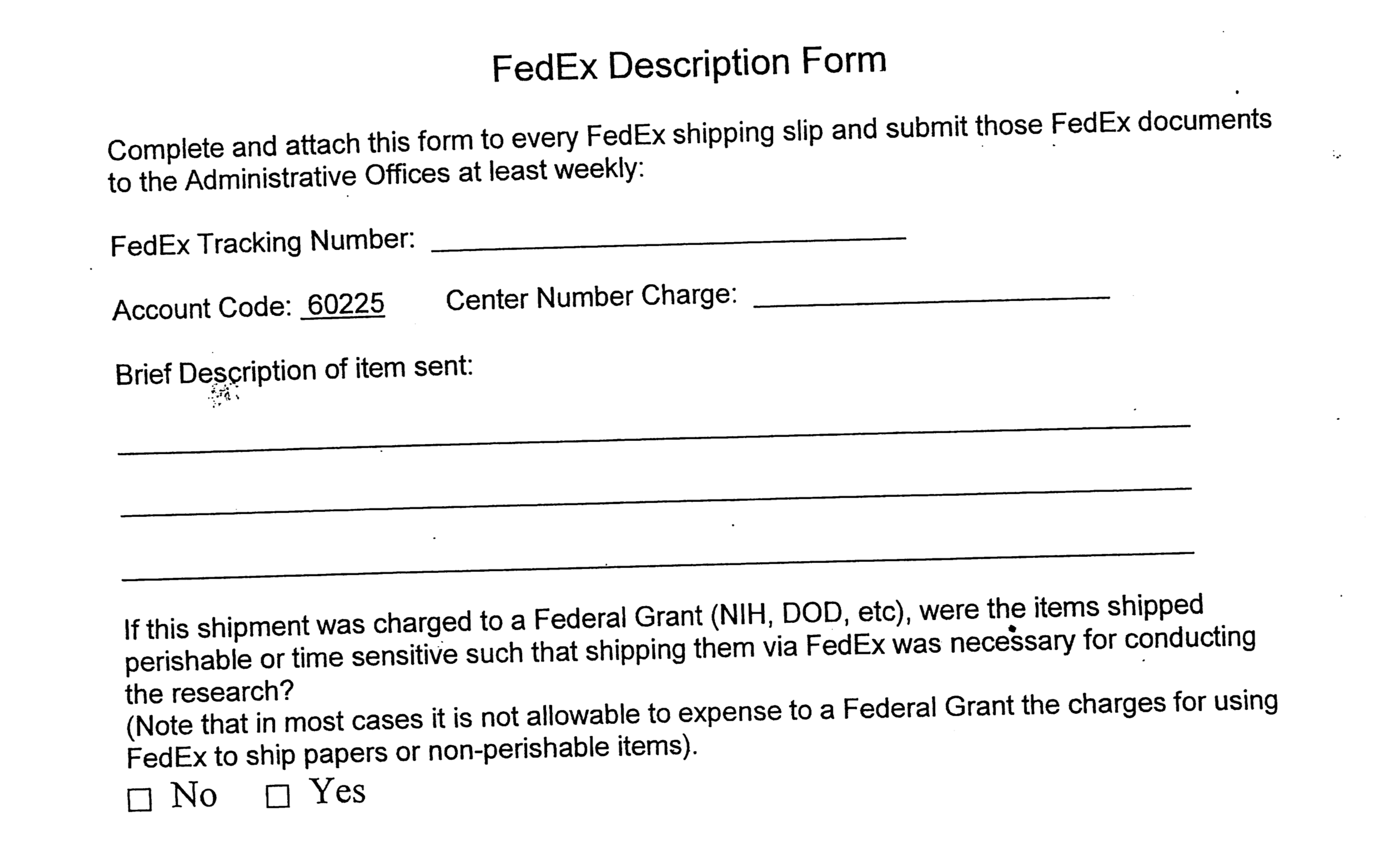
Documentation
It will be necessary for some departments to provide a justification for use of NIH funds for shipping. This can be done using the following form: